Syllabus:
Introduction: Application, History, Market Scenario, Reference Model and Overview, Wireless Local Loop and Cellular system.
Wireless Transmission: Frequencies, Signals, Antennae, Signal Propagation, Multiplexing, Modulation, Spread Spectrum.
MAC Layer: Specialized MAC, SDMA, FDMA, TDMA – Fixed TDM, Classical ALOHA, Slotted, ALOHA, CSMA, DAMA, PKMA, Reservation TDMA. Collision Avoidance, Polling, Inhibit Sense Multiple Access, CDMA.
Broadcasting: Unidirectional Distribution Systems, Digital Audio Broadcasting, Digital Video Broadcasting, Convergence of Mobile and Broadcasting Techniques.
Content Outline
- 1. Introduction to Mobile and Wireless Communications
- 1.1 Applications of Mobile and Wireless Communication
- 1.2 Historical Development of Wireless Communication
- 1.3 Market Scenario
- 1.4 Reference Model and Overview
- 1.5 Wireless Local Loop (WLL)
- 1.6 Cellular System
- 2. Wireless Transmission
- 2.1 Frequencies in Wireless Communication
- 2.2 Signals
- 2.3 Antennas
- 2.4 Signal Propagation
- 2.5 Multiplexing
- 2.6 Modulation
- 2.7 Spread Spectrum
- 3. Medium Access Control (MAC) Layer
- 3.1 Channel Allocation-Based MAC Techniques
- 3.1.1 Fixed Assignment
- FDMA (Frequency Division Multiple Access)
- TDMA (Time Division Multiple Access)
- SDMA (Space Division Multiple Access)
- 3.1.2 Dynamic Assignment
- CDMA (Code Division Multiple Access)
- Reservation TDMA
- 3.1.1 Fixed Assignment
- 3.2 Access Control Method-Based MAC Techniques
- 3.2.1 Random Access
- ALOHA (Pure ALOHA and Slotted ALOHA)
- CSMA (CSMA/CD and CSMA/CA)
- Inhibit Sense Multiple Access
- Collision Avoidance Systems
- 3.2.2 Controlled Access
- Polling
- Token Passing
- DAMA (Demand Assigned Multiple Access)
- PRMA/PKMA (Packet Reservation Multiple Access)
- 3.2.1 Random Access
- 3.3 Comparison of MAC Techniques
- 3.4 Wireless MAC Implementation Examples
- 3.1 Channel Allocation-Based MAC Techniques
- 4. Broadcasting
- 4.1 Unidirectional Distribution Systems
- 4.2 Digital Audio Broadcasting (DAB)
- 4.3 Digital Video Broadcasting (DVB)
- 4.4 Convergence of Mobile and Broadcasting Techniques
Section 1. Introduction to Mobile and Wireless Communications
PYQ: Explain Wireless Communication System with block diagram. (2021, 15 marks)
Mobile and wireless communication is the technology that allows devices to communicate without physical connections (like wires). It uses radio waves and satellites to send and receive data. This technology is essential for mobile phones, Wi-Fi, GPS, and many other applications. It enables people to connect and share information anytime, anywhere.
Key Features of Mobile and Wireless Communication:
- Mobility: Users can move freely while staying connected.
- Wireless: No physical cables needed; uses radio waves or satellite signals.
- Real-time Communication: Enables instant voice, video, and data exchange.
- Scalability: Can support a large number of users and devices.
- Flexibility: Can be used in various environments (urban, rural, indoors, outdoors).
Block Diagram of Wireless Communication System
Digital Data → Modulated Signal → Radio Waves → Received Signal → Reconstructed Data
       Digital Data                                Reconstructed Data
            │                                           ▲
┌───────────▼─────────┐                       ┌─────────|───────────┐
│    TRANSMITTER      │                       │      RECEIVER       │
│─────────────────────│                       │─────────────────────│
│ • Information Source│                       │ • Receiving Antenna │
│ • Source Encoder    │                       │ • RF Amplifier      │
│ • Channel Encoder   │                       │ • Demodulator       │
│ • Digital Modulator │                       │ • Channel Decoder   │
│ • RF Transmitter    │                       │ • Source Decoder    │
│ • Transmit Antenna  │                       │ • Information Output│
└───────────|─────────┘                       └───────────▲─────────┘
            │                                             │
 Signal Transmission                               Received Signal
 (Modulated RF signal                          (with noise & interference)
  as Radio Waves)                                         │
            └───────────────┐           ┌─────────────────┘
                    ┌───────▼───────────▼────┐
                    │         CHANNEL        │
                    │────────────────────────│
                    │ • Radio Waves          │
                    │ • Air Medium           │
                    │ • Noise                │
                    │ • Interference         │
                    └────────────────────────┘
Signal Flow Explanation:
- Digital Data: Original information (voice, text, video) enters the system
- Modulated Signal: Digital data is converted to analog signal suitable for transmission
- Radio Waves: Modulated signal is transmitted through air as electromagnetic waves
- Received Signal: Antenna captures the radio waves from the wireless channel
- Reconstructed Data: Original information is recovered through demodulation and decoding
Components of Wireless Communication System:
-
Transmitter: It is responsible for sending the data from the source to the receiver. It includes:
- Information Source: Generates the message/data to be transmitted
- Source Encoder: Compresses data to reduce redundancy
- Channel Encoder: Adds error correction/detection codes
- Digital Modulator: Maps digital data to analog signals
- RF Transmitter: Amplifies signal to required power level
- Transmit Antenna: Converts electrical signals to radio waves
-
Channel: It is the medium through which the signal travels from transmitter to receiver. It includes:
- Radio Waves: The actual signal that carries the information
- Air Medium: The space through which radio waves travel
- Noise: Unwanted signals that can interfere with the transmission
- Interference: Signals from other sources that can disrupt the communication
-
Receiver: It receives the transmitted signal and converts it back to usable data. It includes:
- Receiving Antenna: Captures radio waves from air
- RF Amplifier: Boosts weak received signals
- Demodulator: Extracts original data from modulated signal
- Channel Decoder: Detects/corrects transmission errors
- Source Decoder: Decompresses data to original form
- Information Output: Delivers final message to user
Real-World Example: When you make a phone call:
- Your voice → Transmitter processes it → Sends radio waves → Other phone receives waves → Converts back to voice → Person hears you
1.1 Applications of Mobile and Wireless Communication
Mobile and wireless communication technologies are used in many areas of our daily lives. They have transformed how we communicate, work, and access information. Here are some key applications:
Major Applications:
-
Mobile Phones & Voice Communication: The most common use. People can call or message each other from anywhere. Useful in both personal and professional life.
-
Internet Access: Mobile data and Wi-Fi help people browse the internet using smartphones, tablets, or laptops. Allows online shopping, video calls, learning, etc.
-
Banking & Payments: Mobile banking, UPI apps (like Google Pay, PhonePe) use wireless communication for secure transactions. Widely used in India for quick and easy payments.
-
Remote Work & Learning: Online classes, Zoom meetings, Google Meet – all possible due to wireless networks like 4G, 5G, and Wi-Fi.
-
Navigation and GPS: Apps like Google Maps use wireless signals (satellite + mobile networks) to show location and help with directions.
-
Healthcare: Remote patient monitoring, telemedicine, and emergency services use wireless communication.
-
IoT (Internet of Things): Smart homes, smart cities, smart agriculture all use wireless tech to connect devices like lights, fans, ACs, and sensors.
-
Military and Defense: Used for secure, fast communication between units, drones, satellites, and command centers.
-
Broadcasting & Entertainment: TV channels, online streaming (Netflix, YouTube), and radio services are broadcasted wirelessly.
-
Disaster Management: During floods, earthquakes, or emergencies, wireless communication helps in rescue operations and coordination.
1.2 Historical Development of Wireless Communication
PYQ: Give history of evolution of mobile radio communication. (2024, 7.5 marks)
PYQ: Explain the different generation in cellular wireless networks. (2022, 8 marks)
Wireless communication has evolved significantly over the past century, leading to the advanced mobile networks we use today. Here’s a brief history:
- 1895: Guglielmo Marconi sent the first wireless signal (radio communication).
- 1900s: AM and FM radio developed.
- 1940s–50s: Military used walkie-talkies and early mobile radios.
- 1973: First mobile phone call by Martin Cooper (Motorola).
- 1980s (1G): Analog mobile phones, analog voice communication.
- 1990s (2G): Digital mobile phones (SMS, calls), digital voice transmission.
- 2000s (3G): Mobile internet, video calls, faster data rates (up to 2 Mbps).
- 2010s (4G): High-speed internet (up to 100 Mbps), HD video streaming, LTE (Long Term Evolution) technology
- 2020s (5G): Ultra-fast internet (up to 10 Gbps), low latency, IoT connectivity, smart cities, and autonomous vehicles.
- Future: 6G (expected around 2030) with even faster speeds, advanced AI integration, and more IoT devices.
1.3 Market Scenario of Mobile and Wireless Communication
The mobile and wireless communication market has grown rapidly over the years and is now one of the biggest industries in the world.
Current Global Scenario:
-
Massive User Base: Billions of people worldwide use mobile phones and internet services daily. In India alone, there are over 1.1 billion mobile subscribers.
-
Telecom Industry Growth: The telecom sector is growing due to increasing demand for internet, smart devices, and digital services. Companies like Jio, Airtel, Vodafone, and BSNL are major players in India.
-
Rise of 5G Technology: 5G rollout is happening in many countries including India. It offers high-speed internet, better coverage, and supports advanced applications like IoT and smart cities.
-
Affordable Smartphones: Companies like Xiaomi, Realme, and Samsung provide feature-rich phones at low prices, boosting the market.
-
Digital India Movement: Government initiatives like “Digital India” have pushed for wider mobile and internet adoption.
-
Mobile App Economy: Huge growth in apps for banking, education, entertainment, healthcare, etc. Startups and tech companies are thriving due to mobile access.
-
Rural Connectivity: Efforts are being made to improve mobile and internet access in rural and remote areas.
Future Market Trends:
- More users shifting to 5G.
- Use of AI and IoT in mobile networks.
- Rise in mobile payments and digital wallets.
- More investment in rural and satellite communication.
- Growth of smart devices and wearables (like smartwatches, fitness trackers).
- Increased focus on cybersecurity and data privacy in mobile communication.
1.4 Reference Model and Overview of Wireless Communication
To understand how mobile communication works, we use a Reference Model — it shows the structure or layers of the communication system and how data travels between sender and receiver.
What is a Reference Model?
A reference model is like a blueprint that explains how data flows in a communication system. It helps in understanding how different parts of the system work together.
Common Reference Model: OSI Model (Open Systems Interconnection)
The OSI Model has 7 layers, and each layer performs a specific function in communication:
   ┌──────────────────────┐
7  │  Application Layer   │ ← User Interface, HTTP, FTP, Email, VoIP
   ├──────────────────────┤
6  │  Presentation Layer  │ ← Data Formatting, Compression, Encryption, Decryption
   ├──────────────────────┤
5  │   Session Layer      │ ← Connection/Session Management
   ├──────────────────────┤
4  │  Transport Layer     │ ← Data Transfer (TCP/UDP)
   ├──────────────────────┤
3  │   Network Layer      │ ← Routing (IP Addressing)
   ├──────────────────────┤
2  │   Data Link Layer    │ ← Error Handling, Framing, MAC Addressing
   ├──────────────────────┤
1  │  Physical Layer      │ ← Signal Transmission (Radio Waves, Modulation)
   └──────────────────────┘
Mnemonic: "All People Should Try New Delicious Pizza"
How Does the OSI Model Apply to Mobile Communication?
In mobile communication, the OSI model helps us understand how data is sent and received:
- Application Layer (Layer 7): User interacts with apps like WhatsApp or Facebook.
- Presentation Layer (Layer 6): Data is formatted (e.g., images, text) and encrypted for security.
- Session Layer (Layer 5): Manages the connection between the mobile device and the server.
- Transport Layer (Layer 4): Ensures data is sent correctly, using protocols like TCP for reliable delivery.
- Network Layer (Layer 3): Determines the best path for data to travel through the network (using IP addresses).
- Data Link Layer (Layer 2): Organizes data into frames and checks for errors during transmission.
- Physical Layer (Layer 1): Converts data into electrical signals or radio waves and transmits them through antennas.
1.5 Wireless Local Loop (WLL)
PYQ: Wireless local loop (2021, 5 marks)
What is Wireless Local Loop?
- WLL is a system that connects subscribers (users) to the telephone network using wireless technology instead of traditional copper wires like in landline phones.
- It is mainly used to provide telephone and internet services in areas where it is difficult or expensive to lay cables (e.g., rural or hilly areas).
Components of WLL:
- Telephone Exchange: The central system that connects calls between different users and routes them to the public telephone network.
- Base Station: A fixed station that connects to the telephone exchange. Acts like a mini mobile tower.
- Subscriber Unit: A wireless phone or terminal used by the user to make calls or access the internet.
- Radio Link: The wireless connection between the base station and subscriber unit.
Block Diagram of WLL System
         Telephone Exchange
               │
       ┌───────▼────────┐
       │  Base Station  │
       │ (Wireless Hub) │
       └───────┬────────┘
               │  Radio Link (Wireless)
       ┌───────▼────────┐
       │Subscriber Unit │
       │(Wireless Phone)│
       └────────────────┘
How it Works:
- User dials a number using their wireless phone (subscriber unit).
- The signal is sent to the nearest base station using radio waves.
- The base station forwards the call to the telephone exchange.
- The exchange connects the call to the desired recipient, either within the same WLL network or to the public telephone network.
- For internet access, the base station connects to the internet service provider (ISP) and provides data services to the subscriber unit.
Advantages of WLL:
- Quick Deployment: No need for extensive cabling, making it faster to set up.
- Cost-Effective: Cheaper than laying physical cables in remote areas.
- Flexibility: Can be used in areas where traditional landline services are not feasible.
- Mobility: Some WLL systems allow limited mobility, meaning users can move within a certain area while still being connected.
Disadvantages of WLL:
- Limited Range: The signal strength decreases with distance from the base station.
- Interference: Wireless signals can be affected by physical obstacles (like buildings) and weather conditions.
- Lower Data Speeds: Compared to wired connections, WLL may offer lower data speeds and reliability.
Example in India:
- Reliance WLL: One of the first and most popular WLL services in India, launched in the early 2000s.
- BSNL WLL: Bharat Sanchar Nigam Limited (BSNL) also provided WLL services in rural areas to improve connectivity.
1.6 Cellular System
PYQ: Describe the operation of cellular system. (2024, 7.5 marks)
PYQ: Explain the cellular system architecture in detail. (2023, 8 marks)
What is a Cellular System?
A cellular system is a type of mobile communication network that allows mobile devices to communicate wirelessly over large areas by dividing the coverage area into smaller regions called cells. Each cell has its own antenna or base station, which connects to the wider network. All these cells work together to provide seamless communication for mobile users as they move around.
Cellular System Architecture
The cellular system architecture consists of several interconnected components that work together to provide wireless communication services.
┌──────────────────────────────────────────────────────┐
│                  Public Switched                     │
│                 Telephone Network (PSTN)             │
└────────────────┬─────────────────────────────┬───────┘
                 │                             │
                 ▼                             ▼
┌────────────────────────────┐   ┌────────────────────────────┐
│    Mobile Switching Center │   │    Mobile Switching Center │
│           (MSC-1)          │   │           (MSC-2)          │
└──────────┬─────────┬───────┘   └──────────┬─────────┬───────┘
           │         │                      │         │
           ▼         ▼                      ▼         ▼
        ┌─────┐   ┌─────┐                ┌─────┐   ┌─────┐
        │ BS1 │   │ BS2 │                │ BS3 │   │ BS4 │
        └──┬──┘   └──┬──┘                └──┬──┘   └──┬──┘
           │         │                      │         │
           ▼         ▼                      ▼         ▼
        /‾‾‾‾‾\   /‾‾‾‾‾\                /‾‾‾‾‾\   /‾‾‾‾‾\
       / Cell1 \ / Cell2 \              / Cell3 \ / Cell4 \
        \_____/   \_____/                \_____/   \_____/
           │         │                      │         │
           ▼         ▼                      ▼         ▼
          📲        📲                    📲        📲
        Device 1   Device 2              Device 3   Device 4
Structure Components:
- Public Switched Telephone Network (PSTN): The traditional landline network that connects calls between different users, including those in the cellular system.
- Mobile Switching Center (MSC): The central component that manages mobile calls and data sessions. It connects calls between mobile devices and the PSTN or other mobile networks. Each MSC serves multiple base stations.
- Base Station (BS): The radio tower that communicates with mobile devices within its coverage area (cell). Each base station is responsible for a specific cell and connects to the MSC.
- Cell: A geographical area covered by a base station. Each cell has its own frequency band to avoid interference with neighboring cells.
- Mobile Devices: The end-user devices (like smartphones, tablets) that connect to the cellular network through the base stations.
How Cellular System Works:
- User Device Initiation: A mobile device (like a smartphone) sends a signal to the nearest base station when a call or data request is made.
- Base Station Communication: The base station receives the signal and communicates with the Mobile Switching Center (MSC) to route the call or data request.
- Call/Data Routing: The MSC checks the user's location and routes the call or data to the appropriate destination, which could be another mobile device or a landline.
- Handover Process: If the user moves to another cell during a call, the system performs a handover to transfer the connection to the new base station without dropping the call.
- Call/Data Completion: Once the call or data session is completed, the MSC updates the user's location in its database to ensure future requests are routed correctly.
Cellular System Operation:
- Cell Division: The coverage area is divided into smaller cells, each served by a base station.
- Frequency Reuse: The same frequencies can be used in non-adjacent cells to maximize spectrum efficiency.
- Handover: When a user moves from one cell to another, the system seamlessly transfers the call/data connection to the new base station without interruption.
- Interference Management: The system manages interference between cells to ensure clear communication.
- Roaming: Users can access services outside their home network by connecting to other networks, allowing for broader coverage.
Generations of Cellular Networks:
- 1G (First Generation): First generation of mobile networks, analog technology, basic voice calls only.
- 2G (GSM/Global System for Mobile Communications): First digital cellular system, introduced SMS and basic data services at 9.6-14.4 kbps.
- 3G (UMTS/Universal Mobile Telecommunications System): Introduced high-speed data services (up to 2 Mbps), video calls, and better internet access with enhanced multimedia capabilities.
- 4G (LTE/Long Term Evolution): Offers high-speed internet (up to 100 Mbps), HD video streaming, VoLTE (Voice over LTE), and low latency for improved user experience.
- 5G (NR/New Radio): The latest generation, providing ultra-fast internet speeds (up to 10 Gbps), extremely low latency (1ms), massive device connectivity, and comprehensive support for IoT devices.
Advantages of Cellular System:
- Efficient use of frequency (due to reuse)
- Supports mobility (users can move from cell to cell)
- High capacity (can serve many users)
- Scalable (can add more cells as demand increases)
Disadvantages of Cellular System:
- Limited range (each cell has a limited coverage area)
- Interference (signals from nearby cells can interfere)
- Complex infrastructure (requires many base stations and coordination)
Applications of Cellular Systems:
- Voice Communication: Making phone calls using mobile devices.
- Data Services: Internet browsing, video streaming, and online gaming.
- Location-Based Services: GPS navigation, ride-hailing apps, and location tracking.
Section 2. Wireless Transmission
Wireless transmission is the process of sending data or signals through the air using electromagnetic waves instead of wires. It is the backbone of mobile communication, enabling devices to connect and communicate without physical connections.
2.1 Frequencies in Wireless Communication
What is Frequency?
- Frequency refers to the number of times a signal oscillates (vibrates) per second.
- Frequency = number of wave cycles per second
- It is measured in Hertz/Hz (1 Hz = 1 cycle per second).
- Higher frequencies: more data capacity but shorter range
- Lower frequencies: longer range but less data capacity
Key Frequency Bands
| Band | Usage |
|---|---|
| 30 kHz – 300 kHz | AM radio |
| 30 MHz – 300 MHz | FM radio, VHF TV |
| 300 MHz – 3 GHz | Mobile phones (2G–5G), Wi-Fi |
| 3 GHz – 30 GHz | 5G, satellite communication |
Frequency Management
- Licensed bands: Require government permission (e.g., mobile networks)
- Unlicensed bands: Free to use (e.g., Wi-Fi, Bluetooth)
- Frequency reuse: Same frequency used in non-adjacent cells to maximize spectrum efficiency
2.2 Signals
What is a Signal?
- A signal is an electrical or electromagnetic wave that carries information (such as voice, video, or data) from one place to another.
- In wireless communication, signals are transmitted through the air using radio waves.
Types of Signals
Signals carry information over wireless channels and can be either analog or digital.
-
Analog Signals
- Continuous signals that vary over time in a smooth way.
- Examples: Voice in a traditional phone call, analog TV.
- Can have infinite values at any point.
- More susceptible to noise and distortion, making them less reliable for long-distance communication.
-
Digital Signals
- Represent information as sequences of discrete values (0s and 1s).
- Examples: Internet data, digital TV.
- Easier to process, more reliable, and less prone to noise.
- Can be compressed and encrypted, making them more efficient for transmission.
Key Signal Properties
-
Amplitude (A)
- Represents the strength or intensity of the signal.
- Higher amplitude = stronger signal.
-
Frequency (f)
- Refers to the number of oscillations per second.
- Higher frequency means higher data transmission speed but shorter range.
-
Phase (ϕ)
- Describes the position of a signal at any point in its cycle.
- Important for modulating signals in communication.
-
Wavelength (λ)
- The distance between two consecutive points in a wave (like two peaks).
- Wavelength and frequency are inversely related: Higher frequency = shorter wavelength.
Signal Propagation in Wireless Systems
Signals interact with the environment during propagation through:
- Reflection – Signals bounce off obstacles (buildings, walls)
- Refraction – Signals bend when passing through different media
- Diffraction – Signals bend around corners/obstacles
- Scattering – Signals disperse in multiple directions due to small objects
Noise and Distortion
- Noise: Unwanted random signals that interfere with transmission (e.g., static in calls)
- Distortion: Signal alteration during transmission causing information inaccuracy
Signal to Noise Ratio (SNR)
- Ratio of desired signal power to noise power
- Higher SNR = better communication quality with less interference
Analog vs Digital Signals in Wireless Communication
| Feature | Analog Signals | Digital Signals |
|---|---|---|
| Representation | Continuous values | Discrete values (0s and 1s) |
| Transmission | Prone to noise and distortion | Less affected by noise |
| Bandwidth Usage | Requires more bandwidth | Efficient bandwidth usage |
| Example | AM/FM Radio, old phones | Wi-Fi, cellular networks |
Digital signals are preferred for their reliability and efficient use of bandwidth.
2.3 Antennas
What is an Antenna?
- An antenna is a device used to transmit and receive radio waves (electromagnetic signals) in wireless communication.
- It converts electrical signals into electromagnetic waves (radio waves) for transmission and vice versa for reception.
- Transmitting antenna sends data into the air.
- Receiving antenna collects the data from the air.
Types of Antennas
- Omni-directional – sends signals in all directions.
- Directional – sends signals in a specific direction.
-
Omnidirectional Antenna
- Radiates signals equally in all directions (360° in a horizontal plane).
- Commonly used in mobile phones and Wi-Fi routers.
- Provides coverage over a broad area.
-
Directional Antenna
- Focuses energy in a specific direction to increase range and signal strength.
- Example: Parabolic dishes used in satellite communication.
- Typically used in point-to-point communication systems.
-
Dipole Antenna
- One of the simplest types of antennas, consisting of two equal-length conductors.
- Often used in basic communication systems and radio receivers.
-
Array Antenna
- Made of multiple elements working together to focus the signal in a particular direction.
- Example: MIMO (Multiple Input, Multiple Output) systems used in 4G/5G for better data throughput.
Antenna Properties
-
Gain
- Ability to focus energy in a particular direction
- Measured in dBi (decibels over isotropic)
-
Beamwidth
- Angular width of the area covered by antenna's signal
- Narrow beamwidth = more focused signal
-
Polarization
- Orientation of the electric field (vertical, horizontal, circular)
- Important for reducing interference
-
Bandwidth
- Frequency range over which antenna operates effectively
-
Directivity
- How well antenna focuses energy in a specific direction
Applications
- Mobile Phones: Small omnidirectional antennas
- Wi-Fi: Coverage for homes/offices
- Satellite: Directional antennas/dishes
- Broadcasting: Large antennas for wide coverage
2.4 Signal Propagation
What is Signal Propagation?
- Signal propagation refers to the way radio waves travel through the atmosphere from the transmitter to the receiver.
- It is influenced by several factors like terrain, weather, and obstacles in the environment.
Factors Affecting Signal Propagation
-
Distance
- Signal strength decreases with distance
- Free-space loss: Signal power reduction as waves spread
-
Obstacles and Terrain
- Buildings, trees, hills can block/reflect waves
- Line-of-sight communication works best with unobstructed path
-
Atmospheric Conditions
- Rain, fog, snow affect signals (especially higher frequencies)
- Rain attenuation: Signal reduction due to precipitation
-
Reflection, Refraction, Diffraction
- Reflection: Signals bounce off large objects
- Refraction: Signals bend through different atmospheric layers
- Diffraction: Signals bend around obstacles
-
Interference
- Other systems' signals cause interference
- Multipath interference: Multiple copies of same signal arrive from different paths
Types of Propagation Models
-
Free-Space Model
- Assumes clear path between sender and receiver with no obstacles
- Signal gets weaker as distance increases (follows inverse square law)
- Mainly used for satellite communications
- Simple formula: Signal loss = 32.45 + 20log₁₀(frequency in MHz) + 20log₁₀(distance in km)
-
Ground Wave Propagation
- Signals travel along Earth's surface
- Works best at low frequencies (below 2 MHz)
- Affected by ground type and landscape
- Used for AM radio
- Can travel beyond the horizon by following Earth's curve
- Signal weakens with greater distance and higher frequency
-
Skywave Propagation
- Signals bounce off the ionosphere (upper atmosphere) back to Earth
- Allows communication beyond visual range
- Works well with medium/high frequencies (3-30 MHz)
- Changes with day/night, seasons, and sun activity
- Used in shortwave and ham radio
- Can bounce multiple times for very long distances
-
Line-of-Sight (LOS) Propagation
- Requires direct, clear path between sender and receiver
- Common at very high frequencies (VHF/UHF and above)
- Maximum range limited by Earth's curvature
- Simple range formula: distance (km) = 3.57 × √(antenna height in meters)
- Used for microwave links, satellites, and cell phones
- Needs clear space around signal path (Fresnel zone) for best results
-
Obstruction Models
- Study how signals weaken when passing through or around obstacles
- Different models for different scenarios:
- Knife-edge model: How signals bend over sharp objects like hills
- Multiple knife-edge: Accounts for several obstacles in a row
- Bullington model: Simplified approach for hilly terrain
- Okumura-Hata: For urban areas with buildings
- COST-231: Updated version of Hata for higher frequencies (up to 2 GHz)
2.5 Multiplexing
PYQ: Discuss the multiplexing techniques. (2022, 7 marks)
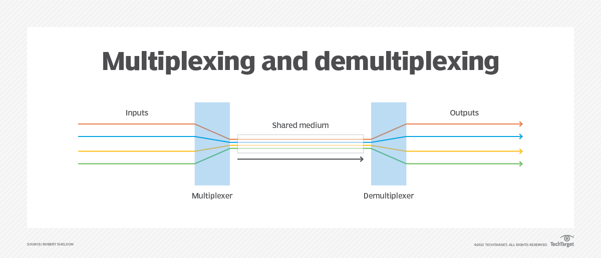
What is Multiplexing?
- Multiplexing is the technique of combining multiple signals into one signal and sending them over a single shared communication channel or medium to save bandwidth and improve efficiency.
- Demultiplexing is the reverse process, where the combined signal is separated back into individual signals at the receiver's end.
Types of Multiplexing
-
Frequency Division Multiplexing (FDM)
- In FDM, the available bandwidth is divided into several smaller, non-overlapping frequency bands. Each signal is transmitted at a different frequency.
- Used in: Radio, TV broadcasting, telephone systems.
-
Time Division Multiplexing (TDM)
- In TDM, the available time is divided into fixed time slots. Each signal is assigned a specific time slot for transmission, allowing multiple signals to share the same channel.
- Used in: Digital telephony, data communication systems.
Types of TDM: - Synchronous TDM (STDM): Fixed time slots for each signal, even if some signals are inactive.
- Asynchronous TDM (ATDM): Time slots allocated dynamically based on demand, allowing more efficient use of bandwidth.
-
Wavelength Division Multiplexing (WDM)
- WDM is a type of FDM used in optical fiber communication. It combines multiple light signals at different wavelengths (colors) into a single fiber. Each wavelength carries a separate signal.
- Used in: Fiber optic communication, high-speed internet.
-
Code Division Multiplexing (CDM)
- In CDM, each signal is assigned a unique code, allowing multiple signals to be transmitted simultaneously over the same frequency band. The receiver uses the unique codes to separate the signals.
- Used in: 3G mobile networks, CDMA, GPS.
-
Space Division Multiplexing (SDM)
- In SDM, multiple physical channels (like different fibers or antennas) are used to transmit multiple signals simultaneously. Each signal has a dedicated path (space) for transmission which are then combined at the receiver.
- Used in: Fiber optics, MIMO (Multiple Input Multiple Output) systems in wireless communication.
Comparison of Multiplexing Techniques
| Multiplexing Type | Description | Advantages | Disadvantages |
|---|---|---|---|
| FDM | Divides bandwidth into frequency bands | Efficient use of bandwidth, supports multiple signals | Requires precise frequency allocation, susceptible to interference |
| TDM | Divides time into slots for each signal | Simple implementation, good for digital signals | Fixed slots can waste bandwidth, requires synchronization |
| WDM | Combines signals at different wavelengths in fiber optics | High capacity, efficient for long-distance communication | Requires expensive equipment, limited by fiber characteristics |
| CDM | Uses unique codes for each signal | High capacity, resistant to interference | Complex encoding/decoding, requires synchronization |
| SDM | Uses dedicated physical paths for each signal | High capacity, can handle multiple signals simultaneously | Requires more infrastructure, complex management |
Advantages of Multiplexing
- Efficient Bandwidth Use: Allows multiple signals to share one channel
- Cost-Effective: Reduces need for multiple physical lines
- Increased Capacity: Handles more signals without additional bandwidth
- Better QoS: Can prioritize certain signals or services
- Flexibility: Supports various types of signals (voice, data, video) over the same medium
Disadvantages of Multiplexing
- Complexity: Requires sophisticated equipment for multiplexing/demultiplexing
- Synchronization: TDM requires precise timing to avoid data loss
- Interference: FDM can suffer from interference between channels
- Signal Degradation: Over long distances, signals may degrade, requiring repeaters or amplifiers
- Limited by Technology: Each multiplexing technique has its own limitations based on technology and medium used
Applications of Multiplexing
- Telecommunications: Used in phone systems, internet, and TV
- Satellite Communication: Maximizes limited bandwidth with FDM/TDM
- Broadcasting: FM radio and TV use FDM for multiple channels
- Mobile Networks: CDMA technology uses CDM for voice/data
- Data Centers: WDM in fiber optics for high-speed data transfer
2.6 Modulation
PYQ: Modulation (2021, 5 marks) PYQ: Briefly explain the different types of Digital Modulation techniques. (2023, 7 marks)
What is Modulation?
- Modulation is the process of modifying a carrier wave (typically a high-frequency signal) to encode information from a message signal (like voice, video, or data) for transmission over a communication channel.
- The goal is to ensure that the signal can travel efficiently over long distances and be decoded accurately at the receiver's end.

Why is Modulation Necessary?
- Long-Distance Transmission - Low-frequency signals can't travel far due to high interference and attenuation. Modulation shifts them to higher frequencies for better transmission.
- Multiplexing - Allows multiple signals to share one channel, improving bandwidth efficiency.
- Reduced Noise - Higher frequency signals are less affected by interference and noise.
- Antenna Efficiency - Higher frequencies require smaller antennas, making mobile devices more practical.
Types of Modulation
There are several types of modulation based on how the carrier wave is modified:
-
Amplitude Modulation (AM)
- In AM, the amplitude (or strength) of the carrier wave is varied in proportion to the message signal.
- Example: AM radio broadcasting.
- Drawback: Prone to noise and interference, as noise affects the amplitude of the signal.
-
Frequency Modulation (FM)
- In FM, the frequency of the carrier wave is varied according to the amplitude of the message signal.
- Example: FM radio broadcasting.
- Advantage: More resistant to noise and interference compared to AM.
-
Phase Modulation (PM)
- In PM, the phase of the carrier wave is changed in accordance with the message signal.
- Example: Used in some satellite communications.
- Combination: Often combined with FM to create Frequency-Shift Keying (FSK) or Phase-Shift Keying (PSK) in digital communication.
-
Quadrature Amplitude Modulation (QAM)
- QAM combines both AM and FM by varying both the amplitude and phase of the carrier wave. It is used for high-data-rate communication.
- Example: Used in digital TV and cable modems.
- Advantage: Efficient use of bandwidth and provides higher data rates.
Digital Modulation Techniques
-
Binary Amplitude Shift Keying (BASK)
- In BASK, the amplitude of the carrier wave is switched between two levels, representing binary '1' and '0'.
- Application: Basic form of digital modulation used in early communication systems.
-
Binary Frequency Shift Keying (BFSK)
- BFSK involves changing the frequency of the carrier wave between two distinct values, representing binary '1' and '0'.
- Application: Used in low-bandwidth digital communication systems like pager systems.
-
Binary Phase Shift Keying (BPSK)
- BPSK involves changing the phase of the carrier signal between two distinct values, representing binary '1' and '0'.
- Application: Used in satellite communication and Wi-Fi networks.
Modulation vs. Demodulation
-
Modulation
- The process of encoding the message onto the carrier wave to enable transmission.
- Key Process: Message signal → Modulation → Transmitted signal.
-
Demodulation
- The process of extracting the original message from the received modulated signal.
- Key Process: Received signal → Demodulation → Message signal.
Advantages of Modulation
- Long-Distance Communication - Modulation allows signals to travel over longer distances by shifting them to higher frequencies.
- Multiplexing - Modulation enables multiple signals to be transmitted over the same medium using different frequencies or time slots.
- Efficient Use of Bandwidth - Through modulation, communication systems can efficiently utilize the available frequency spectrum.
- Improved Signal Quality - Modulation helps in minimizing the effects of noise and interference during transmission.
- Compatibility with Antennas - Higher frequency signals allow for smaller antennas, making devices more portable and practical.
Disadvantages of Modulation
- Complexity - Modulation and demodulation require complex circuitry and algorithms, increasing system complexity.
- Signal Distortion - Modulated signals can be affected by distortion, leading to loss of information.
- Bandwidth Requirements - Some modulation techniques require more bandwidth than others, which can limit the number of channels available.
2.7 Spread Spectrum
PYQ: Spread Spectrum (2024, 5 marks)
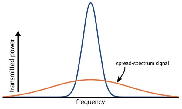
What is Spread Spectrum?
- Spread Spectrum is a technique used in wireless communication to spread the signal over a wide frequency range, much broader than the minimum bandwidth required to transmit the signal.
Why is Spread Spectrum Used?
- Improved Security - Signals spread over wide frequency range are harder to intercept or detect
- Resistance to Interference - Less affected by narrowband interference as only small portions of the spread signal are impacted
- Multipath Fading Resistance - More resilient to signal reflections that cause multipath fading
- Multiple Access - Enables multiple users to share same frequency band simultaneously (used in CDMA)
- Robustness - Provides better performance in noisy environments and allows for more reliable communication
- Reduced Jamming - Makes it difficult for jammers to disrupt the communication as the signal is spread over a wide range
How Spread Spectrum Works
- Spreading: The original signal is multiplied by a pseudo-random code (spreading code) that has a much higher frequency than the original signal.
- Transmission: The spread signal is transmitted over a wide frequency band, making it less susceptible to interference and noise.
- Reception: The receiver uses the same pseudo-random code to demodulate the received signal, extracting the original information.
Types of Spread Spectrum Techniques
-
Frequency Hopping Spread Spectrum (FHSS): In FHSS, the signal rapidly hops between different frequency channels in a pseudo-random sequence. The transmitter and receiver must be synchronized to the same hopping pattern.
- Advantages: Resistant to interference, secure against eavesdropping, and can coexist with other systems.
- Applications: Bluetooth, military communications.
-
Direct Sequence Spread Spectrum (DSSS): In DSSS, the original signal is multiplied by a pseudo-random noise code, spreading the signal over a wider bandwidth. The receiver uses the same code to demodulate the signal.
- Advantages: High resistance to interference, better signal quality, and allows for multiple users (CDMA).
- Applications: GPS, Wi-Fi (802.11b), and cellular networks.
-
Time Hopping Spread Spectrum (THSS): In THSS, the signal is transmitted in short bursts at random time intervals, making it difficult for unauthorized users to intercept.
- Advantages: Provides security and resistance to jamming.
- Applications: Used in some military applications and secure communications.
-
Chirp Spread Spectrum (CSS): In CSS, the signal is modulated by a chirp signal that sweeps through a range of frequencies over time. This technique is particularly useful for long-range communication.
- Advantages: High robustness against interference and multipath fading.
- Applications: LoRa (Long Range) networks for IoT devices.
How Does Spread Spectrum Improve Communication?
- Improved Signal-to-Noise Ratio (SNR) - Increases SNR for clearer reception despite noise
- Reduced Interference - Minimizes interference by spreading signal across broader bandwidth
- Security and Privacy - Difficult for unauthorized users to intercept as only receivers with matching code can decode
- Multiple Access - Enables multiple users to share frequency band using unique codes (CDMA)
- Robustness - More resistant to jamming and multipath fading, ensuring reliable communication
Applications
- Mobile Networks - CDMA technology
- Wi-Fi - Uses DSSS for interference resistance
- GPS - DSSS ensures signals reach despite interference
- Military Communications - FHSS/DSSS for security
- Bluetooth - FHSS for short-range communication
Advantages
- Robustness: Resistant to interference and jamming
- Security: Difficult to intercept or jam
- Multiple Access: Allows multiple users to share the same frequency band
- Improved Signal Quality: Better performance in noisy environments
- Reduced Multipath Fading: More resilient to signal reflections
Disadvantages
- Complexity: Requires sophisticated hardware and algorithms
- Bandwidth Usage: Uses more bandwidth than traditional methods
- Synchronization: Requires precise synchronization between transmitter and receiver
Comparison of Spread Spectrum Techniques
| Technique | Description | Advantages | Disadvantages |
|---|---|---|---|
| FHSS | Rapidly hops between frequency channels | Resistant to interference, secure | Requires synchronization, limited data rate |
| DSSS | Spreads signal by multiplying with pseudo-random code | High resistance to interference, allows multiple users | More complex, requires precise timing |
| THSS | Transmits in short bursts at random intervals | Provides security, resistant to jamming | Limited data rate, requires synchronization |
Section 3. Medium Access Control (MAC) Layer
PYQ: MAC (2023, 2.5 marks)
PYQ: Compare FDMA, TDMA, CDMA and SDMA mechanism in detail. (2024, 15 marks)
The Medium Access Control (MAC) layer is a sublayer of the data link layer in the OSI model that manages how devices access and share the communication medium (like radio waves in wireless networks). It is responsible for controlling access to the shared medium, ensuring that multiple devices can communicate without interference.
What Does the MAC Layer Do?
- Channel Access Control: Determines how devices access the shared medium to avoid collisions and ensure fair access.
- Frame Delimitation: Defines the start and end of data frames to ensure proper transmission and reception.
- Addressing: Assigns unique addresses to devices to identify them on the network.
- Error Detection and Correction: Detects and corrects errors in transmitted frames to ensure data integrity.
- Flow Control: Manages the rate of data transmission between devices to prevent buffer overflow and ensure smooth communication.
Why is the MAC Layer Important?
-
Managing Shared Access In wireless communication, multiple devices share the same communication medium, making it essential to coordinate how data is transmitted. The MAC layer ensures that devices can transmit data without collision and with minimal delay.
-
Supporting Multiple Users The MAC layer allows multiple devices to share the same frequency channel by assigning different access methods, enabling systems like Wi-Fi and cellular networks to support many users simultaneously.
MAC Techniques Classification
MAC (Medium Access Control) Techniques
│
├──► Based on Channel Allocation
│    ├──► Fixed Assignment
│    │    ├──► FDMA (Frequency Division Multiple Access)
│    │    ├──► TDMA (Time Division Multiple Access)
│    │    └──► SDMA (Space Division Multiple Access)
│    │
│    └──► Dynamic Assignment
│         ├──► CDMA (Code Division Multiple Access)
│         └──► Reservation TDMA
│
└──► Based on Access Control Method
     ├──► Random Access
     │    ├──► ALOHA
     │    │    ├──► Pure ALOHA
     │    │    └──► Slotted ALOHA
     │    ├──► CSMA (Carrier Sense Multiple Access)
     │    │    ├──► CSMA/CD (Collision Detection)
     │    │    └──► CSMA/CA (Collision Avoidance)
     │    ├──► Inhibit Sense Multiple Access
     │    └──► Collision Avoidance Systems
     │
     └──► Controlled Access
          ├──► Polling
          ├──► Token Passing
          ├──► DAMA (Demand Assigned Multiple Access)
          └──► PRMA / PKMA (Packet Reservation Multiple Access)
Figure 3.1: MAC techniques classification hierarchy
3.1 Channel Allocation-Based MAC Techniques
In channel allocation-based MAC techniques, the available communication resources (such as frequency, time, or space) are divided among multiple users to allow them to communicate without interference.
3.1.1 Fixed Assignment Techniques
Fixed assignment techniques allocate a fixed portion of the channel resources to each user, regardless of their actual communication needs. This approach provides guaranteed access but may result in inefficient use of resources if users don't utilize their allocated portions.
1. Frequency Division Multiple Access (FDMA)
PYQ: Explain the following terms: FDMA and Classical ALOHA (2023, 8 marks)
FDMA divides the available frequency spectrum into non-overlapping frequency bands, with each user assigned a dedicated frequency band for transmission.
Working Principle:
- The entire available frequency spectrum is divided into separate frequency bands
- Each user is allocated a unique frequency band for transmission
- Users can transmit continuously within their assigned frequency band
- Guard bands are used between channels to prevent interference
   ^
   |
F  |   User 1   User 2   User 3   User 4
r  |     |        |        |        |
e  |     v        v        v        v
q  |  +------+------+------+------+"
   |
   +-------------------------------->
                 Time
Figure 3.2: FDMA channel allocation
Advantages:
- Simple implementation - no complex coordination needed
- No timing synchronization required
- Continuous transmission possible
- No dynamic coordination required after initial assignment
Disadvantages:
- Inefficient for bursty traffic - bandwidth wasted when user is inactive
- Limited capacity due to fixed allocation
- Susceptible to narrowband interference
- Cannot adapt to varying bandwidth needs
Applications:
- First-generation cellular networks (AMPS)
- Satellite communication systems
- Cable TV distribution
2. Time Division Multiple Access (TDMA)
PYQ: Explain the following terms: TDMA and Slot ALOHA (2022, 8 marks)
TDMA divides the communication channel into time slots, with each user assigned specific time slots for transmission.
Working Principle:
- The available transmission time is divided into sequential time slots
- Each user is allocated specific time slots for transmission
- Users take turns transmitting their data during their assigned slots
- A frame consists of multiple time slots, with each slot dedicated to a specific user
   ^   User 1   User 2   User 3   User 1
   |     |        |        |        |
T  |     v        v        v        v
i  |  +------+------+------+------+"
m  |
e  |
   +-------------------------------->
              Frequency
Figure 3.3: TDMA channel allocation
Advantages:
- Efficient spectrum usage - no frequency guard bands needed
- Flexible allocation - can assign multiple slots to high-demand users
- Power-efficient - devices transmit only during allocated slots
- No near-far problem unlike CDMA
Disadvantages:
- Requires precise time synchronization
- Inefficient for varying traffic - fixed slots whether user has data or not
- Overhead for timing and synchronization
- Limited by number of slots in a frame
Applications:
- Digital cellular systems (GSM)
- Satellite communication networks
- Cordless telephone systems (DECT)
3. Space Division Multiple Access (SDMA)
PYQ: SDMA (2022, 2.5 marks)
SDMA separates users based on their spatial location, allowing frequency reuse across different spatial areas.
Working Principle:
- Uses directional antennas or smart antennas to focus signals in specific directions
- Creates spatial channels for different users, minimizing interference
- Dynamically adjusts antenna radiation patterns to track mobile users
- Often used in conjunction with other techniques like TDMA or FDMA
      /|\     /|\     /|\
       |       |       |
     Cell 1   Cell 2   Cell 3
   (Freq A)  (Freq A)  (Freq A)
Figure 3.4: SDMA with frequency reuse across spatially separated cells
Advantages:
- Increases network capacity through spatial separation
- Improves signal quality by focusing energy where needed
- Reduces interference from other users
- Extends coverage area through focused transmission
Disadvantages:
- Complex implementation requiring advanced antenna systems
- Higher cost due to smart antenna requirements
- Mobility tracking issues with fast-moving users
- Requires accurate location information
Applications:
- Modern cellular networks with sectorized cells
- MIMO systems in 4G/5G networks
- Wi-Fi access points with beamforming
- Satellite communications with spot beams
3.1.2 Dynamic Assignment Techniques
Dynamic assignment techniques allocate channel resources based on actual demand, allowing more efficient use of available resources compared to fixed assignment techniques.
1. Code Division Multiple Access (CDMA)
PYQ: Compare FDMA, TDMA, CDMA and SDMA mechanism in detail. (2024, 15 marks)
CDMA is a spread-spectrum technology that allows multiple users to transmit simultaneously on the same frequency by assigning each user a unique code.
Working Principle:
- Each user is assigned a unique orthogonal code
- Data is multiplied by the spreading code, distributing it across the available spectrum
- Multiple transmissions overlap in time and frequency
- Receivers use the same code to extract the original signal
- Processing gain provides resistance to interference
User 1 Data: 1 0 1 1
Code 1:      1 -1 1 -1 1 -1 1 -1
Transmitted: 1 -1 1 -1 -1 1 -1 1

User 2 Data: 0 1 0 1
Code 2:      1 1 -1 -1 1 1 -1 -1
Transmitted: -1 -1 1 1 -1 -1 -1 -1

Combined:     0 -2 2 0 -2 0 -2 0
Figure 3.5: CDMA spreading and combining example
Advantages:
- Increased capacity compared to FDMA/TDMA
- Better security due to spreading codes
- Resistance to interference and jamming
- Soft handover capability between cells
- Flexible rate adaptation
Disadvantages:
- Complex implementation requiring sophisticated signal processing
- Near-far problem requiring precise power control
- More complex synchronization requirements
- Self-interference from other users
Applications:
- 3G cellular networks (WCDMA, CDMA2000)
- GPS satellite navigation systems
- Military communication systems
- Some wireless LAN technologies
2. Reservation TDMA
Reservation TDMA extends regular TDMA by allowing users to reserve time slots for future transmissions based on their needs.
Working Principle:
- Combines fixed TDMA structure with dynamic reservation capabilities
- Users request specific time slots before transmission
- Once slots are reserved, users have guaranteed access without collisions
- Particularly suited for handling variable bit rate traffic
Advantages:
- More efficient than pure TDMA for bursty traffic
- Provides guaranteed bandwidth when needed
- Better quality of service for time-sensitive applications
- Adapts to changing traffic patterns
Disadvantages:
- Overhead for reservation signaling
- Initial access delay for reservation process
- Complex scheduling algorithms needed
- Less efficient than pure statistical multiplexing for highly variable traffic
Applications:
- Satellite communications
- Wireless networks with mixed traffic types
- Voice and multimedia wireless networks
3.2 Access Control Method-Based MAC Techniques
Access control method-based techniques focus on how devices gain access to the shared medium, ensuring fair and efficient resource usage among multiple devices.
3.2.1 Random Access Techniques
In random access techniques, users attempt to access the channel without centralized coordination, with mechanisms to handle collisions when they occur.
1. ALOHA Protocols
ALOHA was one of the earliest random access protocols developed at the University of Hawaii for wireless networks.
a. Pure ALOHA
Working Principle:
- Transmit data whenever available without checking channel status
- If collision occurs, wait a random time before retransmitting
- No synchronization or coordination between transmitters
- Maximum channel utilization: 18.4%
Transmitter A: |----Packet----|        |--------Packet--------|
               |              |        |                      |
Transmitter B:        |------Packet-----|
                      |                 |
                   Collision         Collision
Figure 3.6: Pure ALOHA collisions
Advantages:
- Extremely simple implementation
- No synchronization required
- Works well for light traffic loads
Disadvantages:
- Poor throughput under heavy loads
- High collision probability as traffic increases
- Unstable at high loads
b. Slotted ALOHA
Working Principle:
- Time is divided into discrete slots of fixed length
- Transmissions can only begin at slot boundaries
- Reduces collision vulnerability period by half
- Maximum channel utilization: 36.8%
Time slots:   |    |    |    |    |    |    |    |
              |    |    |    |    |    |    |    |
Transmitter A:|----|----|Pkt |----|----|----|Pkt |
              |    |    |    |    |    |    |    |
Transmitter B:|----|----|Pkt |----|----|Pkt |----|
              |    |    |    |    |    |    |    |
                         ^              ^
                      Collision      No collision
Figure 3.7: Slotted ALOHA operation
Advantages:
- Better throughput than Pure ALOHA
- Still simple to implement
- Performs well under light to moderate loads
Disadvantages:
- Requires time synchronization
- Still inefficient under heavy loads
- Wastes slots when no device transmits
2. Carrier Sense Multiple Access (CSMA)
PYQ: CSMA (2023, 2.5 marks)
CSMA improves upon ALOHA by listening to the channel before transmission to reduce collision probability.
Working Principle:
- Devices listen to detect if channel is busy before transmitting
- If channel is busy, device follows a specific protocol to determine when to try again
- Different variants implement different strategies for channel access
a. CSMA/CD (Collision Detection)
Working Principle:
- Listen before transmitting
- If collision detected during transmission, abort immediately
- After collision, wait random time before retrying
- Primarily used in wired networks (Ethernet)
Advantages:
- More efficient than ALOHA
- Quick collision resolution
- Well-suited for wired networks
Disadvantages:
- Difficult to implement in wireless networks
- Cannot solve hidden terminal problem
- Efficiency decreases with propagation delay
b. CSMA/CA (Collision Avoidance)
Working Principle:
- Listen before transmitting
- If channel is idle, transmit after a short waiting period
- If channel is busy, back off for a random time
- Uses techniques like RTS/CTS to address hidden terminal problem
- Used in wireless networks (Wi-Fi)
Advantages:
- Better suited for wireless networks than CSMA/CD
- Addresses hidden terminal problem with RTS/CTS (Request-to-Send/Clear-to-Send)
- Reduces collision probability through random backoff
Disadvantages:
- Higher overhead than CSMA/CD
- Increased latency due to collision avoidance mechanisms
- Performance degrades with many active users
CSMA/CD vs CSMA/CA Comparison
| Feature | CSMA/CD | CSMA/CA |
|---|---|---|
| Collision Detection | Detects collisions during transmission | Avoids collisions before transmission |
| Medium Type | Primarily used in wired networks | Primarily used in wireless networks |
| Mechanism | Listens before transmitting, aborts on collision | Listens before transmitting, uses RTS/CTS to avoid collisions |
| Efficiency | More efficient in low-latency environments | More efficient in high-latency environments |
3. Inhibit Sense Multiple Access
Inhibit Sense Multiple Access uses a busy tone to indicate channel status, helping prevent collisions in wireless networks.
Working Principle:
- Uses a separate channel for busy tone
- Receiver generates busy tone when receiving data
- Other stations monitor busy tone channel before transmission
- Helps address hidden terminal problem
Advantages:
- Reduces hidden terminal problem
- Simple implementation compared to RTS/CTS
- Better throughput than basic CSMA
Disadvantages:
- Requires separate channel for busy tone
- Exposed terminal problem still exists
- Additional hardware requirements
4. Collision Avoidance Systems
Collision Avoidance Systems are designed to prevent collisions before they occur, particularly in wireless networks where hidden terminals can cause significant issues. Hidden terminal problem occurs when two devices cannot hear each other but can both hear a third device, leading to potential collisions.
a. MACA (Multiple Access with Collision Avoidance)
Working Principle:
- Uses RTS/CTS (Request-to-Send/Clear-to-Send) control packets
- Sender transmits RTS to receiver
- Receiver responds with CTS if ready
- Nearby nodes hearing CTS defer their transmissions
- Addresses hidden terminal problem
A ─── RTS ───> B ─── CTS ───> C
(Sender)       (Receiver)     (Other node)
Figure 3.8: MACA operation with RTS/CTS exchange
b. MACAW (MACA for Wireless)
Working Principle:
- Enhances MACA with acknowledgments (ACK)
- Improves backoff algorithm
- Adds carrier sensing before RTS
- Better sharing of medium information between nodes
A ─── RTS ───> B ─── CTS ───> A
A ─── DATA ──> B ─── ACK ───> A
Figure 3.9: MACAW operation with RTS/CTS/DATA/ACK exchange
Advantages of Collision Avoidance Systems:
- Effectively addresses hidden terminal problem
- Improves throughput in multi-node scenarios
- Reduces collisions for data packets
Disadvantages:
- Overhead for control packets
- Delay in initial transmission
- Exposed terminal problem still partially present
3.2.2 Controlled Access Techniques
In controlled access techniques, access to the medium is regulated by a centralized control mechanism or a distributed algorithm that ensures only one station transmits at a time.
1. Polling
Polling involves a central controller systematically checking each device to see if it has data to transmit.
Working Principle:
- Central controller polls each station in sequence
- Station transmits only when polled
- After transmission or if no data, control passes to next station
- Provides deterministic access with no collisions
     ┌───┐
     │ C │
     └─┬─┘
  ┌────┼────┐
┌─▼─┐┌─▼─┐┌─▼─┐
│T1 ││T2 ││T3 │
└───┘└───┘└───┘

C = Controller
T = Terminal
Figure 3.10: Centralized polling structure
Types of Polling:
- Roll-Call Polling: Controller polls each terminal in sequence
- Hub Polling: Controller polls only active terminals
- Token Passing: Special token circulates; only terminal with token may transmit
Advantages:
- Guaranteed access without collisions
- Fair allocation of bandwidth
- Predictable performance
- Works well for high loads
Disadvantages:
- Polling overhead
- Single point of failure (controller)
- Increased latency as network grows
- Inefficient for large networks with light traffic
2. Token Passing
Token Passing is a distributed control technique where a special control frame (token) circulates among nodes, with only the token holder allowed to transmit.
Working Principle:
- Special token frame circulates among stations in logical ring
- Station can transmit only when it holds the token
- After transmission or if no data, token passed to next station
- Self-regulating without central controller
Advantages:
- No central controller needed
- Guaranteed access without collisions
- Fair bandwidth allocation
- Predictable performance
Disadvantages:
- Token management overhead
- Lost token recovery mechanisms needed
- Adding/removing stations is complex
- Fixed latency increases with network size
3. Demand Assigned Multiple Access (DAMA)
PYQ: DAMA (2022, 2.5 marks)
DAMA dynamically allocates channel capacity to users based on their requests, optimizing resource usage.
Working Principle:
- Users request bandwidth from central controller when needed
- Controller allocates resources based on availability and priorities
- Resources released when transmission completes
- Particularly useful for satellite and wireless networks
Advantages:
- Efficient use of resources based on actual demand
- Supports varying traffic patterns
- Can implement quality of service priorities
- More efficient than fixed assignment for bursty traffic
Disadvantages:
- Allocation request overhead
- Initial access delay
- Complex central controller required
- Single point of failure
4. Packet Reservation Multiple Access (PRMA/PKMA)
PRMA combines elements of TDMA and random access protocols to efficiently handle mixed traffic types.
Working Principle:
- Frame structure with time slots (like TDMA)
- Contention-based access for unreserved slots (like ALOHA)
- Successful transmission in unreserved slot leads to reservation of that slot in future frames
- Reservation maintained until explicitly released
Frame n:      |R1|C |R3|C |R5|R6|C |C |
Frame n+1:    |R1|R2|R3|C |R5|R6|R7|C |
Frame n+2:    |R1|R2|R3|R4|R5|R6|R7|C |

R = Reserved slot (assigned to a specific user)
C = Contention slot (available for new reservations)
Figure 3.11: PRMA frame structure over time
Advantages:
- Efficiently handles mix of periodic and bursty traffic
- Better performance than pure TDMA for varying traffic
- Supports both constant bit rate and variable bit rate traffic
- Dynamic adaptation to changing traffic patterns
Disadvantages:
- Complex implementation
- Frame synchronization required
- Initial contention phase may result in collisions
- Overhead for reservation mechanism
3.3 Comparison of MAC Techniques
| Technique | Access Method | Coordination | Best For | Limitations |
|---|---|---|---|---|
| FDMA | Fixed assignment | None after allocation | Continuous traffic | Inefficient for bursty traffic, limited capacity |
| TDMA | Fixed assignment | Time synchronization | Predictable traffic | Requires precise timing, wasted slots for inactive users |
| CDMA | Code separation | Power control | Security, capacity | Complex implementation, near-far problem |
| ALOHA | Random access | None | Simple implementation, light traffic | Poor performance under heavy load |
| CSMA/CA | Random with sensing | Distributed | Wireless networks, moderate traffic | Hidden terminal problem, overhead |
| Polling | Controlled access | Centralized | High loads, QoS guarantees | Polling overhead, single point of failure |
| DAMA | Demand-based | Centralized | Satellite communications, mixed traffic | Request overhead, central controller dependency |
3.4 Wireless MAC Implementation Examples
| Technology | Primary MAC Technique | Key Features |
|---|---|---|
| Wi-Fi (IEEE 802.11) | CSMA/CA with DCF/PCF | RTS/CTS option, collision avoidance, distributed coordination |
| Bluetooth | TDD/FHSS/Polling | Master-slave polling structure, frequency hopping |
| GSM | TDMA/FDMA combination | Time slots on different frequency channels |
| LTE | OFDMA (downlink), SC-FDMA (uplink) | Resource block allocation, QoS classes |
| 5G NR | Enhanced OFDMA | Flexible numerology, mini-slots, grant-free access |
Note: In practice, modern wireless systems often combine multiple techniques and add enhancements to address specific challenges in different environments.
Section 4. Broadcasting
PYQ: Digital Audio and Video Broadcasting. (2023, 7 marks) PYQ: Discuss Broadcasting Techniques in detail. (2022, 7 marks) PYQ: Write a short note on Broadcasting techniques. (2021, 7.5 marks)
Broadcasting refers to the transmission of data (such as audio, video, or other information) from a central source to a large audience. It typically involves one-to-many communication, where the signal is transmitted to all users in the coverage area. In the context of mobile and wireless communication, broadcasting has seen significant evolution, especially with the advent of digital technologies and mobile devices.
Broadcasting Techniques
│
├──► Based on Direction of Communication
│    ├──► Unidirectional
│    └──► Bidirectional
│
├──► Based on Type of Content
│    ├──► Audio Broadcasting
│    └──► Video Broadcasting
│
├──► Based on Technology Used
│    ├──► Analog Broadcasting
│    └──► Digital Broadcasting
│
└──► Based on Medium Used
     ├──► Terrestrial Broadcasting
     ├──► Satellite Broadcasting
     └──► Cable Broadcasting
4.1 Unidirectional Distribution Systems
In unidirectional distribution systems, information is transmitted in only one direction — from the source to multiple receivers. This type of system does not allow receivers to send data back to the source. Such systems are typically used in broadcasting applications, where the goal is to transmit content to a large audience.
Features of Unidirectional Systems:
- One-way communication: The source (e.g., a TV station or radio station) sends out signals to all receivers (e.g., television sets or radio receivers) in the coverage area.
- Efficiency: Since the same signal is broadcast to all receivers, these systems are highly efficient for mass distribution of content such as news, entertainment, and information.
- Limited interactivity: Unidirectional systems typically do not support user interaction or feedback. Users can only receive content without sending any data back to the source.
Examples:
- Traditional Radio and TV Broadcasting: Signals are sent from a central transmitter and received by anyone tuned into the right frequency or channel.
- Satellite TV/Radio: Signals are broadcast from satellites to ground receivers, providing services like Direct-to-Home (DTH) TV.
Advantages of Unidirectional Distribution Systems:
- Wide Coverage: Broadcasting can reach a large audience over a wide area without the need for individual connections. ** Cost-Effective: Broadcasting to many users simultaneously reduces costs compared to point-to-point communication.
- Simplicity: Easy to implement and manage, as there is no need for complex routing or addressing schemes.
- Reliability: Digital broadcasting technologies often include error correction and redundancy, ensuring high-quality reception even in challenging conditions.
- Scalability: As the audience grows, the same infrastructure can be used to reach more users without significant changes.
- Low Latency: Broadcasting systems can deliver real-time content with minimal delay, making them suitable for live events and news.
Disadvantages of Unidirectional Distribution Systems:
- Lack of Interactivity: Users cannot send feedback or interact with the content in real-time, limiting engagement.
- Limited Personalization: Broadcasting content is typically generic and may not cater to individual user preferences.
- Potential for Signal Loss: In areas with poor reception, users may experience signal degradation or loss, especially in analog systems.
- Inefficient Use of Bandwidth: Unused bandwidth cannot be shared among users, leading to potential wastage of resources.
- Dependence on Infrastructure: Requires robust transmission infrastructure, which can be costly to maintain and operate.
Unidirectional distribution systems remain a fundamental part of broadcasting technologies, providing a reliable means of mass communication across various media platforms.
4.2 Digital Audio Broadcasting (DAB)
PYQ: Digital Audio and Video Broadcasting. (2023, 7 marks)
Digital Audio Broadcasting (DAB) is a technology that allows the transmission of digital radio signals. Unlike traditional analog radio, which transmits audio signals in an analog format, DAB broadcasts radio programs in a digital format, offering several advantages in terms of sound quality, channel capacity, and reliability.
Advantages of DAB:
- Improved Sound Quality: DAB provides crisper, clearer sound compared to analog radio, reducing static and interference.
- Increased Channel Capacity: DAB allows more radio stations to be transmitted over the same bandwidth. Multiple stations can be broadcast on a single frequency.
- Text and Multimedia: DAB can transmit additional information along with audio, such as song titles, artist names, and even pictures or video clips (in the case of DAB+).
- Robust Reception: Digital signals are less prone to fading and interference, providing more reliable reception, especially in challenging areas like tunnels or rural regions.
DAB+:
- DAB+ is an enhanced version of DAB, using AAC+ audio compression for even better audio quality and efficiency, and allowing more stations to fit into the same spectrum.
- DAB+ has been adopted in many countries around the world for both national and local radio services.
4.3 Digital Video Broadcasting (DVB)
PYQ: Digital Audio and Video Broadcasting. (2023, 7 marks)
Digital Video Broadcasting (DVB) is a suite of standards used for the broadcast transmission of digital television signals. DVB enables broadcasters to deliver high-quality video, audio, and other data to users with greater efficiency and quality compared to analog broadcasting.
DVB Standards:
- DVB-T (Terrestrial): Used for digital terrestrial television, which is transmitted over the air and received by antennas.
- DVB-S (Satellite): Used for satellite television broadcasting, providing wide coverage areas and supporting high-quality TV content.
- DVB-C (Cable): Used for digital television via cable systems, allowing broadcasters to send video and other data over coaxial cables.
- DVB-H (Handheld): A version of DVB for mobile devices, offering digital TV broadcasts to mobile phones, PDAs, and other portable devices.
Advantages of DVB:
- High-Quality Video and Audio: DVB provides superior video and audio quality compared to analog TV, supporting high-definition (HD) and even 4K resolution.
- Multimedia Services: DVB can transmit not just video, but also interactive services, electronic program guides (EPGs), and on-demand video.
- Efficient Spectrum Usage: Digital broadcasting uses the available spectrum more efficiently, allowing for more channels and content to be delivered within the same bandwidth.
4.4 Convergence of Mobile and Broadcasting Techniques
The convergence of mobile and broadcasting technologies refers to the integration of mobile communication systems (like 3G/4G/5G) with traditional broadcasting systems (like DAB and DVB). This convergence enables the delivery of broadcast services over mobile networks, creating new opportunities for interactive, on-demand, and location-based media consumption.
Key Aspects of Convergence:
-
Mobile TV:
- Mobile TV services allow users to watch television programs on their mobile phones or tablets. This can be done through streaming over the internet (via 4G/5G) or through dedicated broadcasting systems like DVB-H. The integration of DVB standards and mobile networks allows for high-quality TV broadcasts to be delivered directly to mobile devices.
-
Interactive Broadcasting:
- Mobile devices provide a platform for interactive broadcasting services, where users can interact with the broadcast content. For example, users can participate in live polls, access extra content like behind-the-scenes footage, or choose their preferred camera angle during a live broadcast.
-
Location-Based Services:
- Mobile devices can leverage GPS and location-based services (LBS) to offer personalized broadcasting. For example, a mobile user in a particular location can receive location-specific news, advertisements, or other media content.
-
Internet Streaming:
- With high-speed mobile networks (like 4G/5G), users can stream digital audio and video content over the internet. Platforms like YouTube, Netflix, and Spotify provide on-demand media consumption, combining aspects of mobile networks and broadcasting.
-
Hybrid Broadcast Broadband TV (HbbTV):
- HbbTV is a European standard that combines broadcasting (DVB) with broadband internet to provide a hybrid platform. It allows users to interact with broadcast content, access on-demand media, and use applications on their TVs, all using their broadband connection.
4.5 Bidirectional Distribution Systems
In bidirectional distribution systems, information can flow in both directions between the source and the receivers. This allows for two-way communication, enabling users to send data back to the source as well as receive data from it. Bidirectional systems are commonly used in applications where user interaction is essential, such as telecommunication networks, interactive TV, live streaming services, and online gaming.
Features of Bidirectional Systems:
- Two-Way Communication: Both the source and receivers can transmit and receive data, enabling interactive applications.
- User Interaction: Users can send feedback, requests, or commands back to the source, enhancing engagement and personalization.
- Dynamic Content Delivery: Content can be tailored based on user preferences and interactions.
Examples:
- Interactive Television (iTV): Users can interact with TV content through remote controls, accessing additional information, voting in polls, or participating in quizzes.
- Video Conferencing Systems: Platforms like Zoom or Skype allow real-time audio and video communication between multiple users.
- Mobile Applications: Apps like WhatsApp or Facebook Messenger enable users to send messages, share media, and interact with content in real-time.
- Live Streaming Services: Platforms like Netflix allow users to provide feedback (like ratings) and request specific content.
- Online Gaming: Multiplayer games allow players to interact with each other and the game environment in real-time.
Advantages of Bidirectional Distribution Systems:
- Enhanced User Experience: Interactivity allows users to engage with content more deeply.
- Personalization: Content can be customized based on user preferences and behavior.
- Real-Time Feedback: Users can provide immediate feedback, improving service quality and responsiveness.
- Increased Engagement: Interactive features keep users engaged longer compared to passive viewing.
Disadvantages of Bidirectional Distribution Systems:
- Complex Infrastructure: Requires more sophisticated technology and infrastructure to support two-way communication.
- Higher Costs: Implementation and maintenance costs can be higher compared to unidirectional systems.
- Potential for Overload: Increased traffic from user interactions can lead to congestion if not managed properly.
- Privacy Concerns: Collecting user data for personalization raises privacy issues that need to be addressed.
4.6 Broadcasting Techniques
Broadcasting techniques refer to the methods and technologies used to transmit audio, video, and other data to a wide audience. These techniques can be categorized based on various factors such as the direction of communication, type of content, technology used, and medium of transmission.
1. Based on Direction of Communication
- Unidirectional Broadcasting: Information is transmitted in one direction from the source to multiple receivers. Examples include traditional radio and TV broadcasting.
- Bidirectional Broadcasting: Information can flow in both directions, allowing for two-way communication. Examples include interactive TV and video conferencing systems.
2. Based on Type of Content
- Audio Broadcasting: Transmitting audio content such as music, news, and talk shows. Examples include FM/AM radio and digital audio broadcasting (DAB).
- Video Broadcasting: Transmitting video content such as TV shows, movies, and live events. Examples include digital video broadcasting (DVB) and streaming services like Netflix.
3. Based on Technology Used
-
Analog Broadcasting: Traditional broadcasting methods that transmit signals in analog format. Examples include AM/FM radio and analog TV.
-
Digital Broadcasting: Modern broadcasting methods that transmit signals in digital format, providing better quality and more features. Examples include DAB for audio and DVB for video.
-
Hybrid Broadcasting: Combines broadcasting with broadband internet to provide interactive services. Examples include Hybrid Broadcast Broadband TV (HbbTV).
4. Based on Medium Used
- Terrestrial Broadcasting: Signals are transmitted over the air using radio waves. Examples include FM/AM radio and DVB-T (terrestrial digital TV).
- Satellite Broadcasting: Signals are transmitted from satellites to ground receivers, providing wide coverage. Examples include DVB-S (satellite digital TV) and satellite radio.
- Cable Broadcasting: Signals are transmitted through coaxial or fiber-optic cables to subscribers. Examples include DVB-C (cable digital TV) and cable radio services.
These notes were compiled by Deepak Modi
Contact: deepakmodidev@gmail.com